In-Situ machining avoids costly shaft removal
Crankshaft stub shaft repair for MAK 12M43C main engine
During major overhaul and repairs to the main engine of a 50,619 DWT bulk carrier, serious damage resulted when the flywheel mounting hub was removed from the crankshaft stub shaft. The extent of the scoring damage to the shaft and hub was so extensive that it was not possible to reinstall the hub onto the shaft after overhaul.
Goltens reviewed the damage and concluded that there were only two options open to carry to out this repair. The first was to remove the shaft and send to it to the makers for machining and the second was to carry out an in-situ machining repair . Both options would require a replacement hub due to the amount of damage in the hub bore. Due to time constraints and commercial reasons it was decided that the preferred method was to carry out the job in-situ.
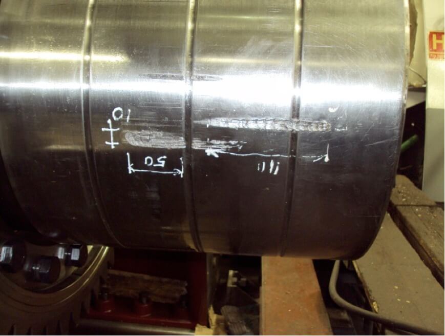
Scoring damage to the crankshaft stub shaft
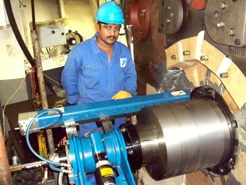
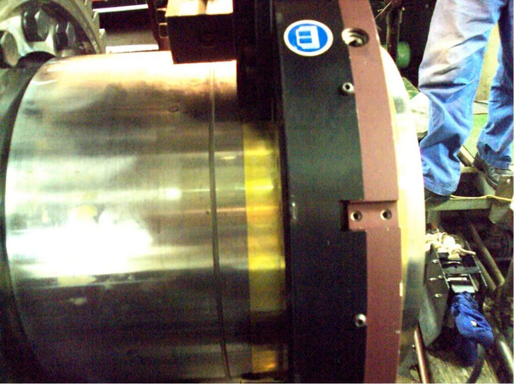
Machining damaged area from journal surface
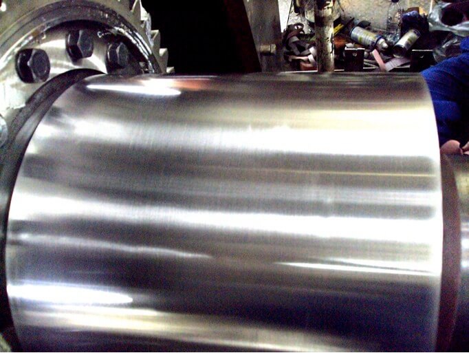
Machined shaft surface (-4mm) pre-machining of oil grooves in the shaft

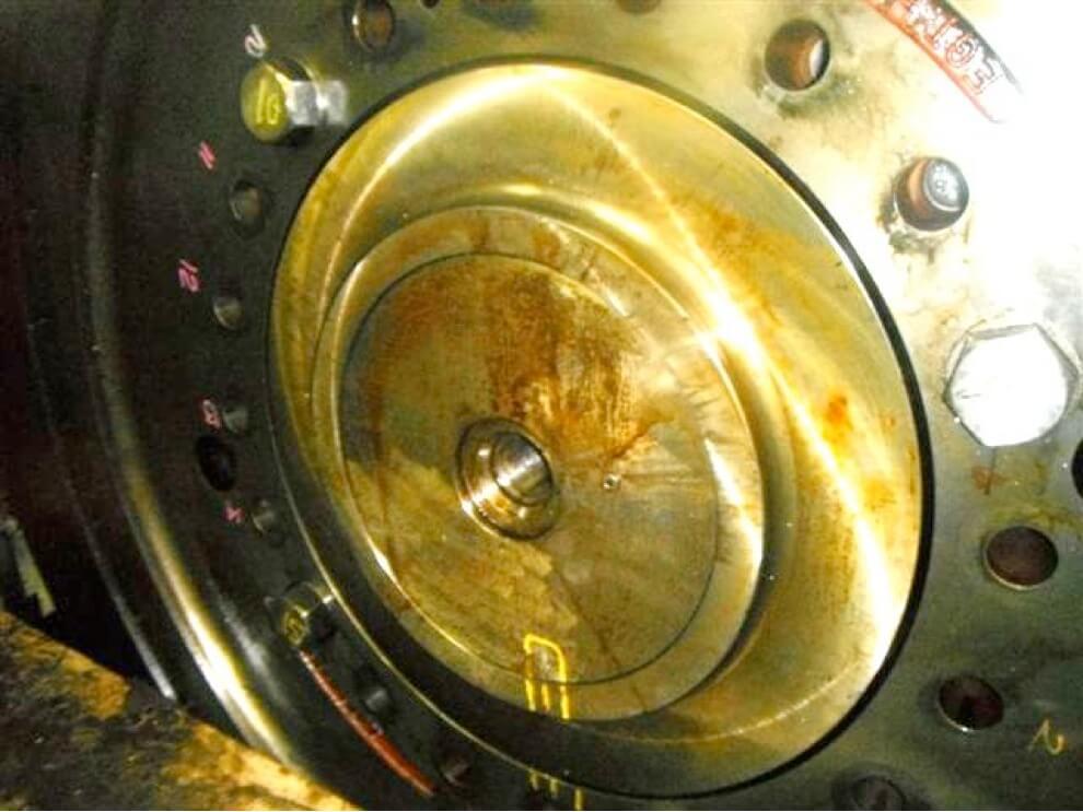
Replacement hub successfully installed on the undersized stub shaft

Machining of replacement oil grooves in the shaft

Completed oil grooves

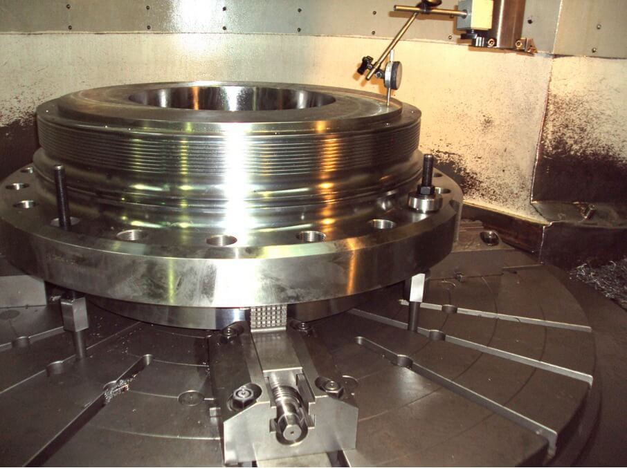
CNC machining of replacement hub in the Goltens workshop
The vessel owners consulted the engine maker and presented the method for proposed repair. After consultation with the makers, the vessel owners were informed by the makers that this type of repair was “not possible In-situ”. Despite this adverse opinion, the owners decided to continue with the In-situ repair that had been suggested and assured by Goltens.
The first stage of the job was to carry out the removal of the damaged area by in-situ machining. This was successfully carried out using Goltens portable lathe machine, with a total of 4.0mm being machined from the 450mm shaft diameter, the dimensional and surface finish parameters were achieved. This in itself posed difficulties as the 1:50 taper on the shaft had to be maintained to within a very tight tolerance, not only the correct angle but the surface finish was also critical to the correct reinstallation.
With the surface finish and dimensional tolerance achieved, the next stage was to replicate the oil grooves that had been present before surface machining. This was achieved by utilizing an orbital pipe-cutting machine and a pre-formed tool to achieve the exact form of the grooves.
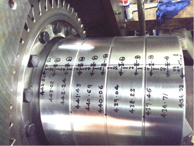
With the shaft machining complete, it was critical to ensure the actual dimensions from the shaft were transferred onto the new hub which had been received as a blank for final machining to be carried out in Goltens’ machine shop.
A series of dimensions were taken at precise distances along the length of the shaft, from this, the exact angle of the shaft was calculated. These calculations were affirmed by manufacturing a set of taper gauges that would be used as comparators on a dummy shaft that was manufactured as a replica of the actual shaft.
After all calculations had been made by Goltens technicians, they were verified by an external third party. The findings were then sent to the engine maker who replied with the theoretical correct dimensions that the hub had to be machined to.
The machining of the taper was carried out on Goltens CNC vertical lathe per the dimensions provided by the maker. The machining was carried out in small increments so as not to risk overcutting the taper. After each cut on the bore of the hub, the earlier made “dummy” was inserted in the bore of the new hub to measure the standoff distance. With the correct standoff distance achieved, the hub was delivered onboard the vessel and installation was carried out by a representative from the engine maker.
PROJECT FACTS
| Bulk Carrier | |
|---|---|
| Engine: | MaK 12M43C |
| Engine Output: | 14,684 HP (500rpm) |
| Material removed from Shaft: | 4.0mm |
| Original Shaft Dia.: | 450mm |
| Conical Ratio: | 1:50 |
CRANKSHAFT REPAIRS
- Machining 4mm from the damaged tapered shaft
- Machine replacement oil grooves in the journal surface
- Manufacture “dummy” tapered shaft for blue fitting in replacement hub
- CNC machining of replacement hub in workshop
IN-SITU MACHINING RESULTS
The installation was completed and the resultant standoff distance was within that specified by the makers. The job was carried out in-situ removing the necessity to remove the crankshaft from the engine and eliminating the extra cost and downtime associated with the disassembly of the engine, transport of the shaft and reassembly of the engine.
Download a PDF of this Resource
(Right click and select "Save File As..." or "Save Link As..." to save)
Download Now